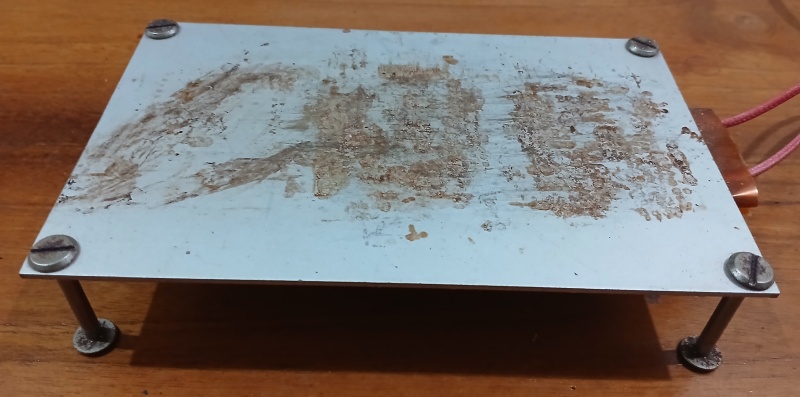
SMT hotplate
I used to process SMT boards by cooking them in a large, heavy frying pan. This worked reasonably well, but the results were sometimes a bit erratic.

A friend gave me a hotplate that he had bought on AliBaba, and couldn't find a use for. I tried using it to process SMT boards, but it uses an PTC element to regulate the temperature, and it got too hot (250C).

After some research, I found that there is a standard temperature profile for SMT reflow ovens: I decided to make a controller that can produce this profile using my hotplate. I would only ever need one controller, so it made sense to use standard parts where possible. These included:
- HLK-PM01 mains to 5V
- MAX31865 Pt100 interface
- ESP-12F
The controller would accept a mains input, both to power the HLK-PM01 module and to feed through a relay to the hotplate. The MAX31865 module measures the resistance of a Pt100 sensor, and passes the information via an SPI interface to an ESP-12 module. Software on the ESP-12 would control the hotplate relay, and also present a web interface to monitor and control progress. Switching mains voltages, and indeed switching a relay, can produce nasty voltage spikes, so I used lots of decoupling capacitors. Here is the circuit diagram:

Pt100 is a good choice for this temperature range, and it is possible to buy encapsulated sensors which should give stable readings in long-term use. Because I was interested in the temperature on the top surface of the PCB, I attached a Pt100 sensor to a PCB using high-temperature silicone sealant: this seemed to give a reasonably accurate temperature reading, compared to an Infra Red thermometer. For maximum accuracy, you should use four wire Pt100 sensors- two wires to provide the sense current, and two more to measure the voltage across the sensor element. This approach eliminates errors due to the voltage drop in the sense current wires. This controller doesn't need particularly high accuracy, so a two wire sensor is adequate.

In a real product, I would have used sockets for the cables in and out, but this is a one-off, so I just used IP65 cable glands: these provide a reasonably secure physical connection. The finished controller looks like this, with the esp-12 on the other side of the board:

I used the Arduino IDE to test the interfaces, then used the ESP SDK to build the complete system.
I wanted to have the possibility of using different temperature profiles: I thought of making a web page to edit the profiles, but decided to simply use structures within the C program- one for each temperature cycle. Controlling the temperature proved to be quite tricky. It took about 20 seconds after turning the relay on before any change in surface temperature occurred. It was therefore necessary to implement a kind of PID controller to track the profile. This is the controller routine:
The hotplate works well for most PCBs but, because all the heat comes from below, it does not work very well with large components like inductors or electrolytic capacitors. It is usually necessary to use a soldering iron on these components afterwards.
