Solar Charger for an Electric motorbike
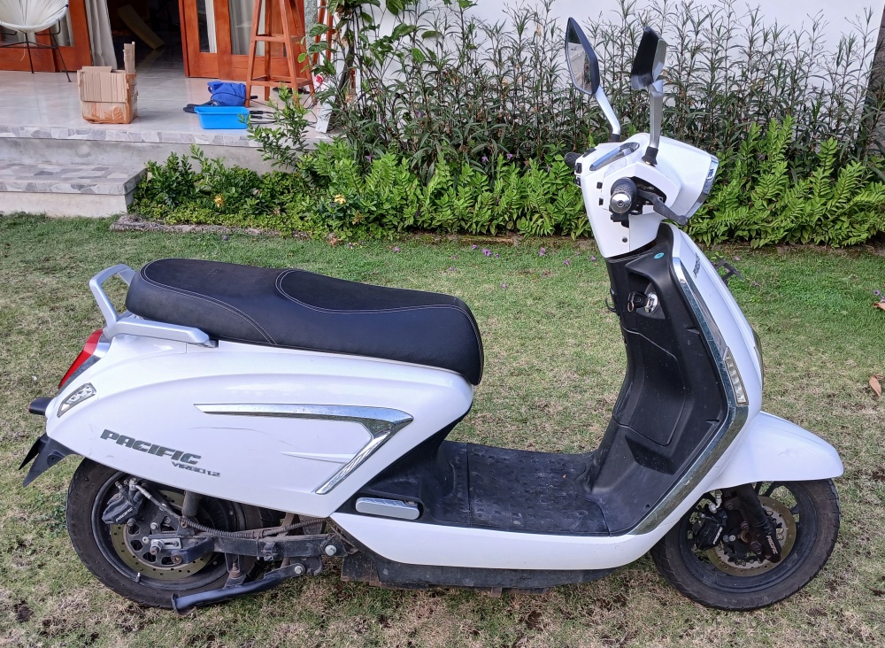
A couple of years ago, I bought an electric motorbike: a Pacific Virgo 1.2. It was intended as an eco-friendly transport solution, as it uses a lot less power than a gasoline motorbike. Generally, I am pleased with it: It rides like a normal motorbike, and can do 45km/h in ECO mode- fast enough for local journeys... except up the steepest hills, and there is only one of those near me.
It's pretty sunny where I live, so I decided to build a solar charger for it. I could have just bought a solar inverter to produce 220V AC, and then feed this into the existing charger... but that would not be very efficient, and anyway, where's the fun in that? Instead, I decided to design a charger that would go directly from the solar panel DC voltage (20 or 40V) to the battery voltage (72V nominal), using a boost regulator. The charger supplied with the bike can deliver 500W, but I decided to start off with a single 100W panel, and maybe move to two panels later. Charging would take longer, but slow charging probably increases the battery life. I've done switch mode power supplies before, but never with such high voltage and power: to be honest, I was a little bit scared.
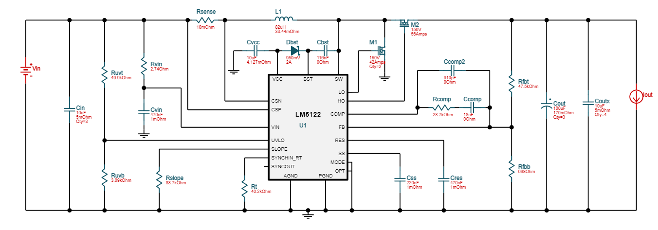
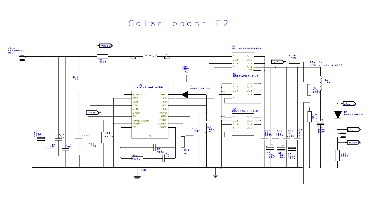
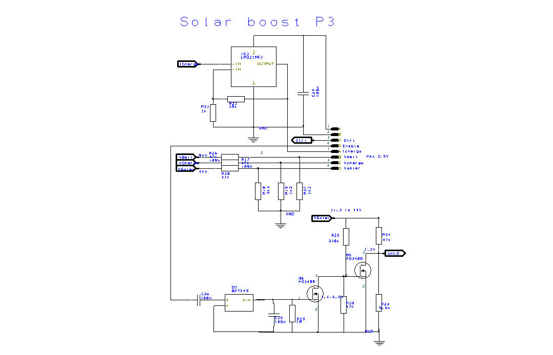
TI provide a circuit design tool (webench) for their LM5122 synchronous boost regulator: I used this to generate a basic circuit, then added a resistor to the feedback circuit. A DAC (driven by a controller) can inject a control voltage through this resistor: the higher the control voltage, the lower the regulator output voltage. Think about that for a moment. Zero volts from the DAC would result in maximum output voltage: not a good situation. To make sure that the regulator only runs when the controller is running, I connected a watchdog circuit to the enable pin of the regulator. The controller has to continuously toggle the input to the watchdog, in order to keep the regulator running. I also added divider networks to reduce the input and output voltages to 0..3.3V, and a header connector to plug in a controller daughter board.
I was able to buy all of the parts except the coil online, mostly from AliExpress. The recommended inductance is 47uH, and it has to transfer a lot of energy on each cycle. After doing some calculations to determine how big it would need to be to prevent saturation, I opted for a 50mm toroid, bifilar wound with about 30 turns of 1.5mm copper wire. This is probably overkill for just 5A, but may as well make it as efficient as possible.
It would probably be unwise to mess about with a home made board when handling 200W, so I got professional double sided boards from JLCPCB. When the boards arrived, I assembled one and connected a 24V power supply to it: it lasted about three seconds before smoke came from it. It turns out that I'd put the LT5122 on the board the wrong way round. I didn't know whether any of the other components were damaged, so I built a completely new board... then started putting off testing it. I knew exactly why the first board had popped, and there was no logical reason for the second board to do the same, but it took several months for me to pluck up courage to test the new board. Eventually I grew tired of the untested board's silent reproach, and connected a power supply. It didn't pop, and before long I had it generating 72W into a dummy load... a long string of 10-ohm resistors. Time to connect a solar panel.
When using a solar panel, it is necessary to use a Maximum Power Point Tracking (MPPT) controller to get the maximum power from the solar panel. If you try to take too much, the voltage from the panel drops, so the boost regulator draws more current to maintain the required output voltage, and the solar panel voltage collapses. You get the maximum power just before this cliff-edge. The amount of current that the battery takes depends on the voltage, so you can control the power but adjusting the boost regulator output voltage.
Each solar panel has a label on the back that quotes the output voltage at maximum power. As long as no part of the solar panel is in shade, this is the only number that you need in order to easily get maximum power from the panel. If the solar voltage is higher than this, you can increase the regulator output voltage: if it is lower, you must reduce the output voltage... quickly. Over the course of the lifetime of the panel, this voltage may change, and it's way more complicated if a shadow falls across part of the panel, but this is a good starting point.
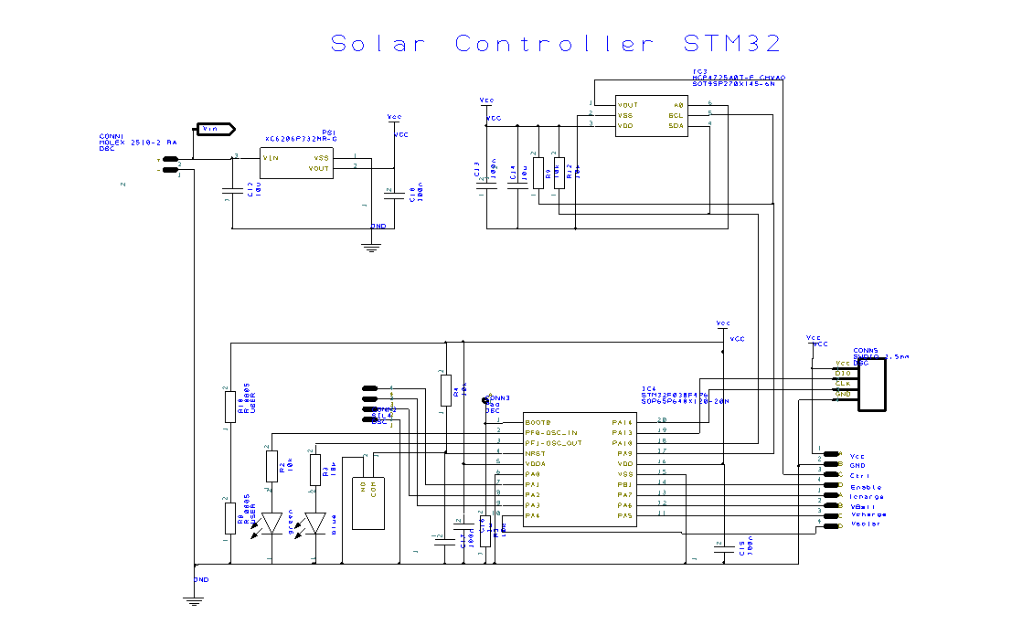
Initially I experimented with an ATMEGA328, however the processor died: it seems relatively easy to damage the bootloader, and you can't reprogram the bootloader without removing the chip from the board. I switched to an STM32, and after a few reset issues, I got it working. By connecting a computer to the serial port on the SMT32, I could monitor the MPPT software.
Connecting the charger to the bike was not straightforward: the connector on the bike looked like an IEC320 C14, but when I tried to plug in a C13 plug, it was too large. In the end, I disconnected the official charger connector, and connected a cable with a SPIKON plug.
With one 100W solar panel, I was able to get a rather disappointing 36W from the boost regulator. It was optimised for two panels, so I decided to buy another panel to connect in series. A tip: if you ever need a two-panel system, buy both panels at the same time. When the second (nominally identical) panel arrived, it was different in a whole number of ways: in particular, it produced more current at a lower peak voltage. With two panels in series, though, I could only get the maximum current of the first panel. Disappointed, I connected it up, and was relieved to get a very satisfactory 120W. With a bit of software tweaking, I raised that to 135W, or 67% of the panels' rated power. Given that the panels were mismatched, I was satisfied.
I really cannot recommend sitting in the sun trying to read a computer screen. I quickly put together an ESP8266 board that sent the serial data from the controller via wifi to my server: I could then monitor the data without venturing into the sun. The next step was to build a mini web site on the ESP8266, so that I could look at the data any time, using any web browser. There are two data displays: one showing the present voltages and currents, and another showing a graph of the day's power and battery voltage. There is another page that would allow me to change the MPTT parameters, but I haven't tried that yet.
The system produces 135W at high noon with a cloudless sky: cloud, haze and trips on my motorbike reduce the daily charge to about 400Wh. The motorbike has a lead acid battery: unlike Lithium batteries, it is very difficult to estimate the state of charge of the battery from the no-load voltage. It therefore took about a month to be convinced that the solar charger was definitely putting more into the battery than I was using. If I do a lot of long trips, or the weather reduces the daily charge, the motorbike is noticeably slower going up the one big hill, but otherwise the bike has performed flawlessly for the whole month. Free transport!
